13 Thin-Walled Pressure Vessels
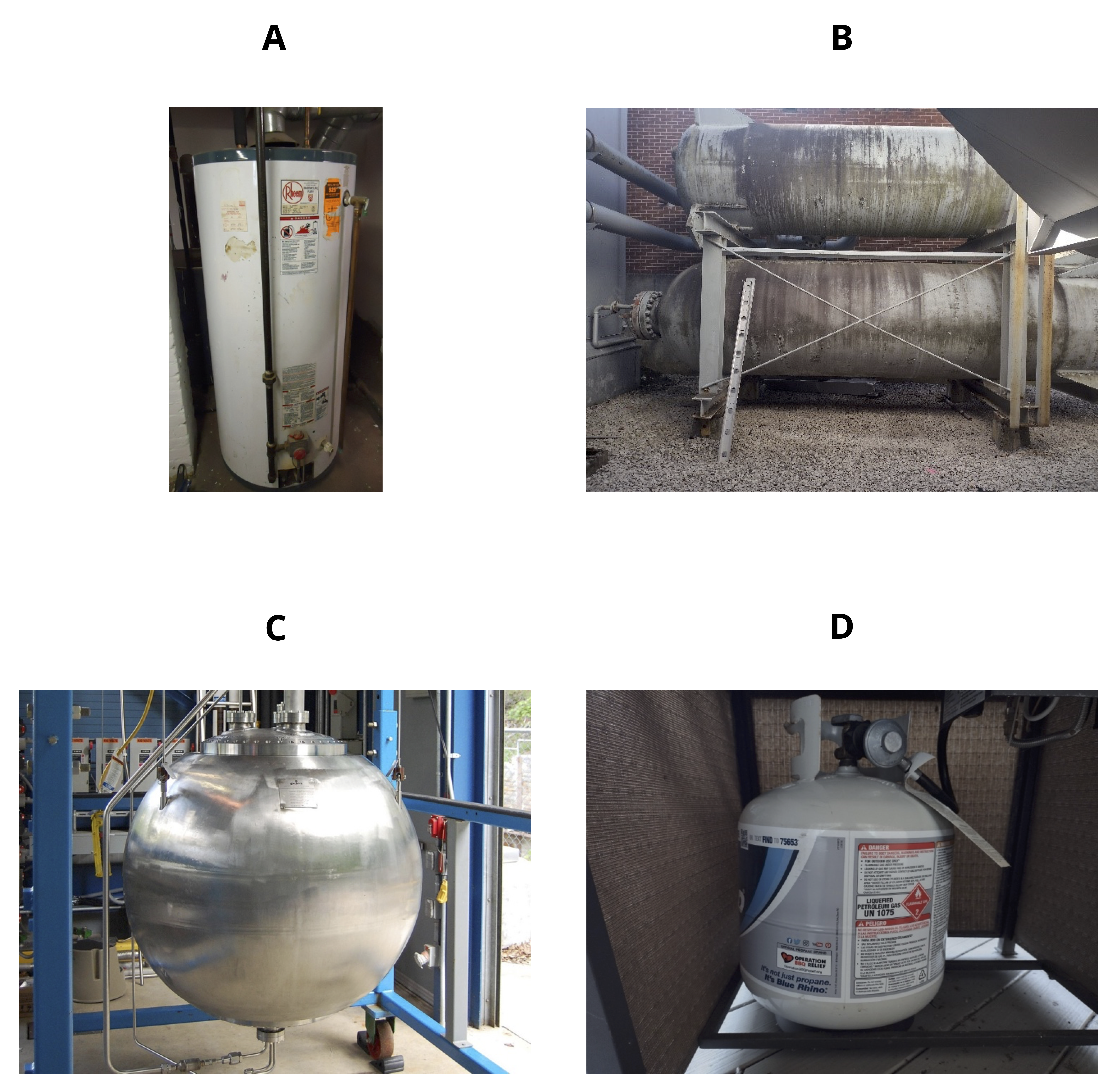
Pressure vessels are storage tanks that are used for storing fluids at high pressure and must therefore be designed to resist this pressure. They are commonly found in factories, power plants, vehicles, and even your own home. Figure 13.1 shows some common applications.
Pressure vessels are necessarily hollow, and a thin-walled pressure vessel is one where ratio
\[ \frac{\text { Inner radius }}{\text { Wall thickness }}>10 \]
This implies that the wall thickness is relatively small compared to the vessel radius. This simplifies our analysis in two ways:
- We can assume that stresses in the vessel walls are uniform across the thickness of the wall.
- We can ignore stress in the radial direction (perpendicular to the vessel wall).
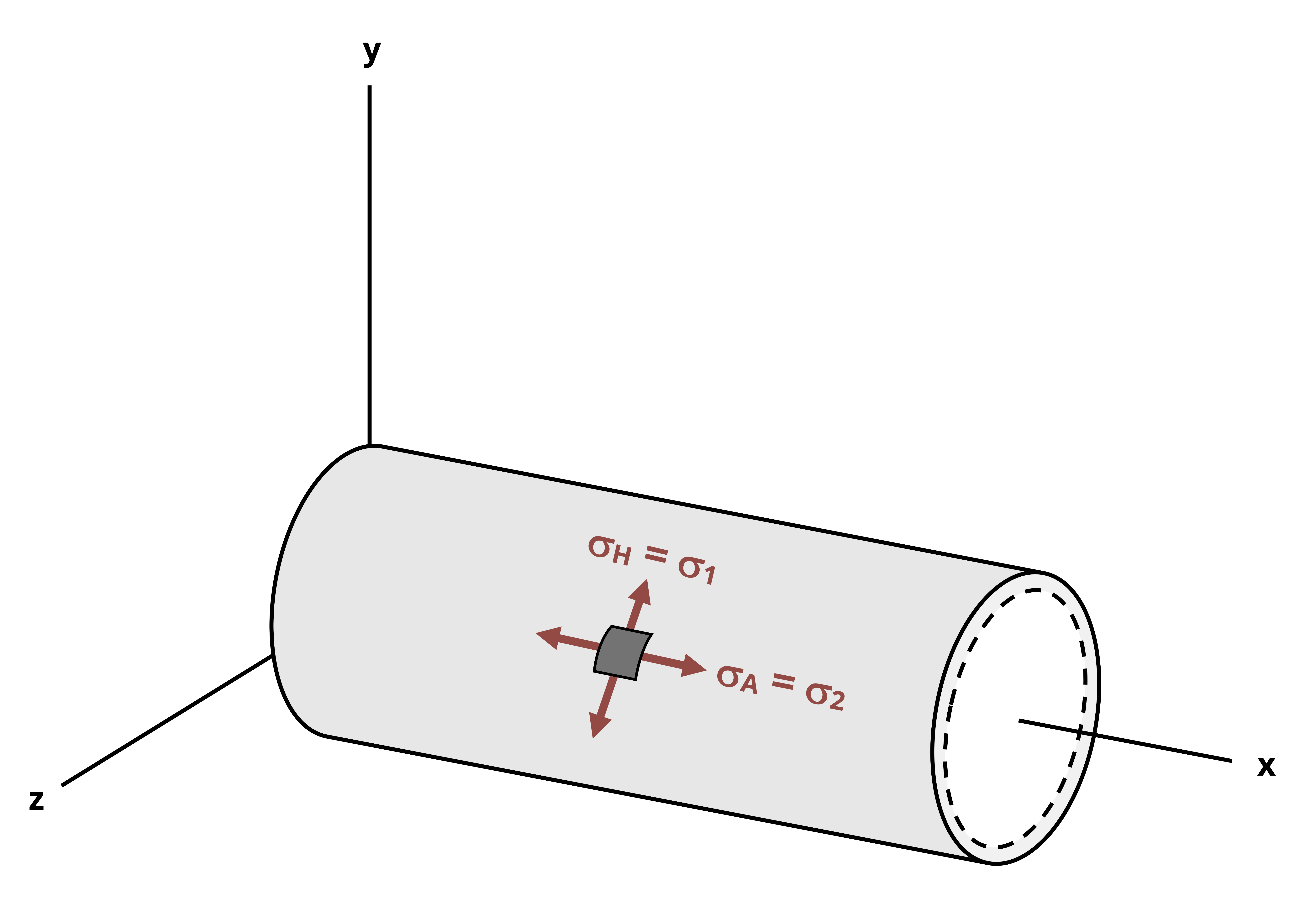
The internal pressure P is typically reported as the gauge pressure, which is defined as the internal pressure minus the atmospheric pressure. This allows us to calculate the stresses directly without needing to account for atmospheric pressure. As we’ll see in this chapter, stresses are generated in the walls of thin-walled pressure vessels in two directions known as the axial stress and hoop stress (Figure 13.2). There is a third stress in the radial direction, but this is small relative to the other stresses and is assumed to be zero in this text.
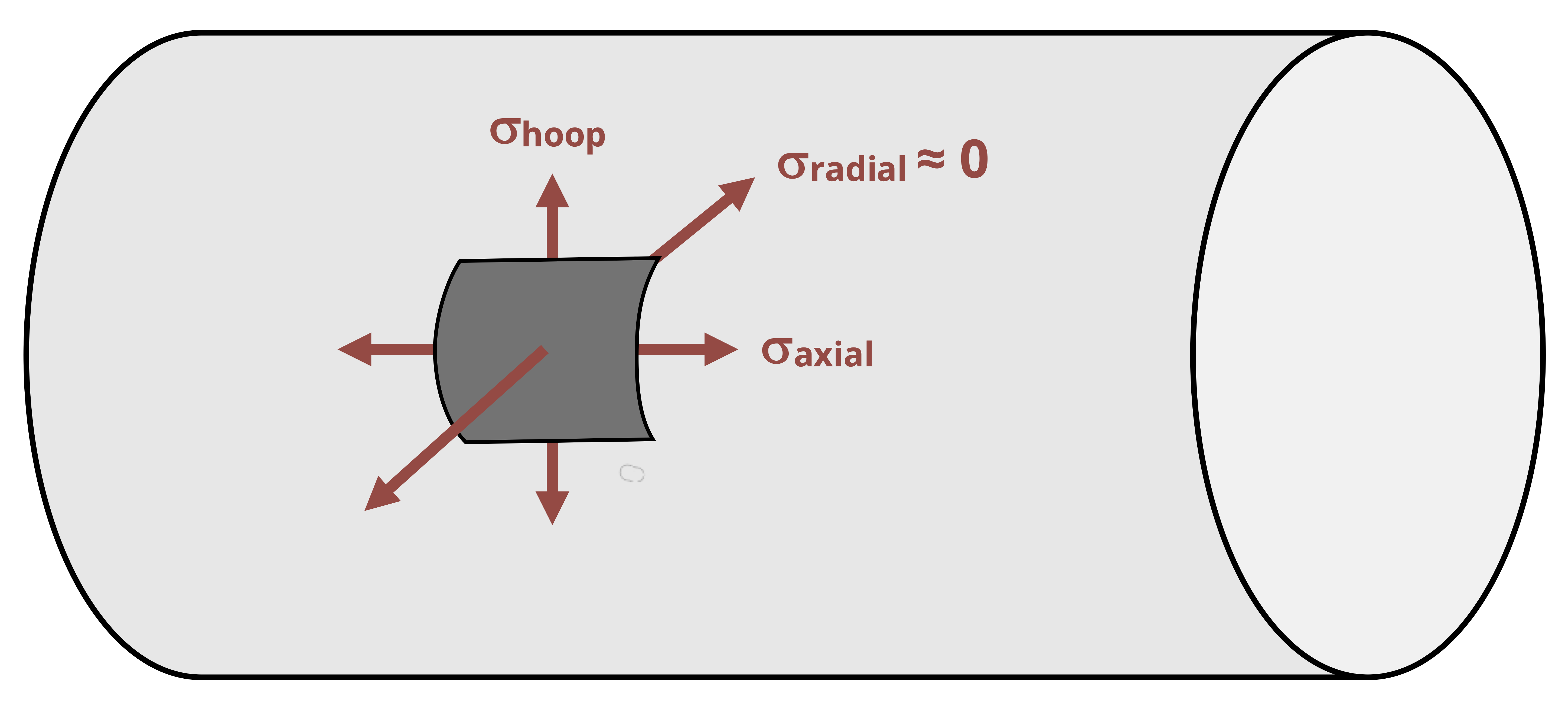
Figure 13.1 shows that thin-walled pressure vessels are commonly either cylindrical or spherical. Section 13.1 discusses the stresses in cylindrical vessels. Section 13.2 discusses the stresses in spherical vessels.
13.1 Cylindrical Pressure Vessels
Click to expand
The equations for stresses in the wall of a cylindrical pressure vessel can be derived with the help of a free body diagram (FBD). A first step is to cut a cross-section through the vessel of interest to expose the fluid inside (Figure 13.3).
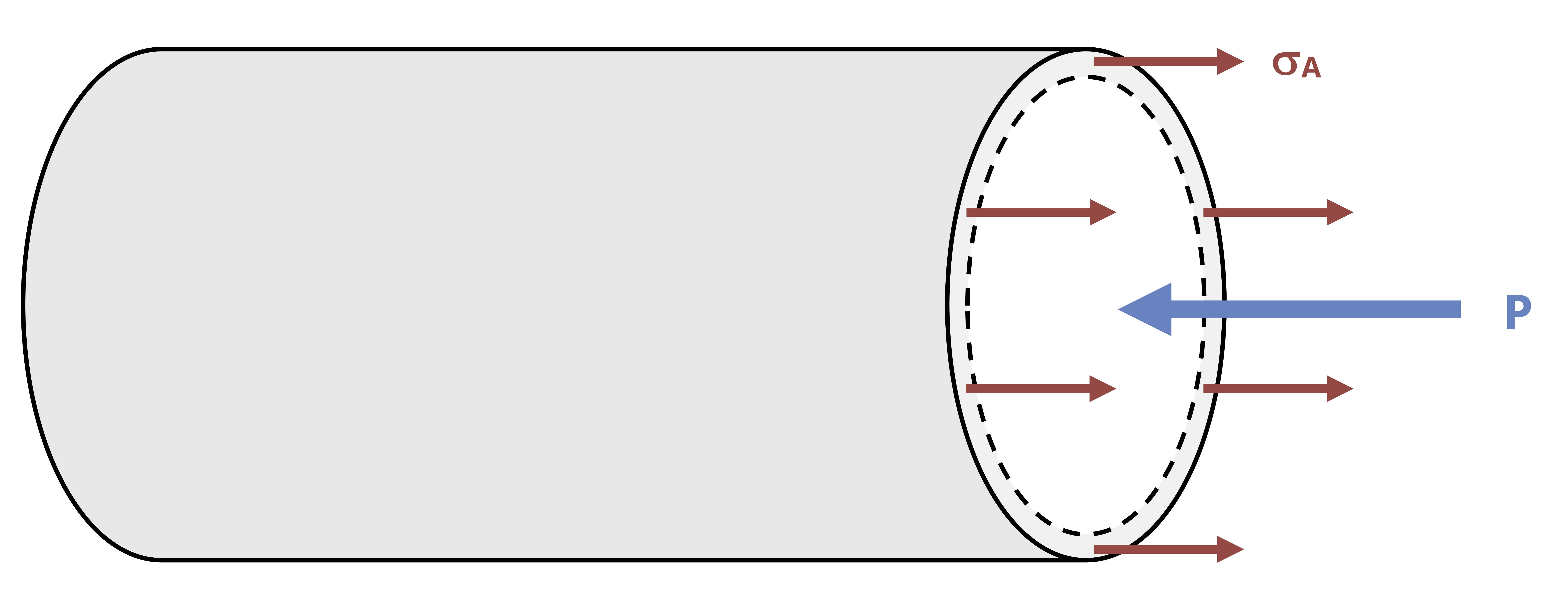
There will be an axial stress from the internal fluid pressure (P) and an axial stress in the walls of the vessel (𝜎𝐴). Since \(\text{stress}=\frac{\text { force }}{\text { area }}\), we can determine the two forces. The fluid pressure acts over a circular area \(A=\pi r_i^2\). The stress in the walls acts over an area equal to the circumference of the vessel multiplied by the wall thickness, \(A=2 \pi r_i t\).
By equilibrium we calculate the following:
\[ \sum F_x=\left(\sigma_A\right)\left(2 \pi r_i t\right)-(P)\left(\pi r_i^2\right)=0 \\ \]
\[ \boxed{\sigma_A=\frac{P r_i}{2 t}}\text{ ,} \tag{13.1}\]
𝜎𝐴 = Axial stress in the wall of the vessel [Pa, psi]
P = Fluid pressure inside the vessel [Pa, psi]
ri = Inner radius of the vessel [m, in.]
t = Wall thickness of the vessel [m, in.]
Similarly, there will be a stress in the lateral direction, referred to as the hoop stress 𝜎H. A vertical cross-section (Figure 13.4) is cut to derive an equation for this stress.
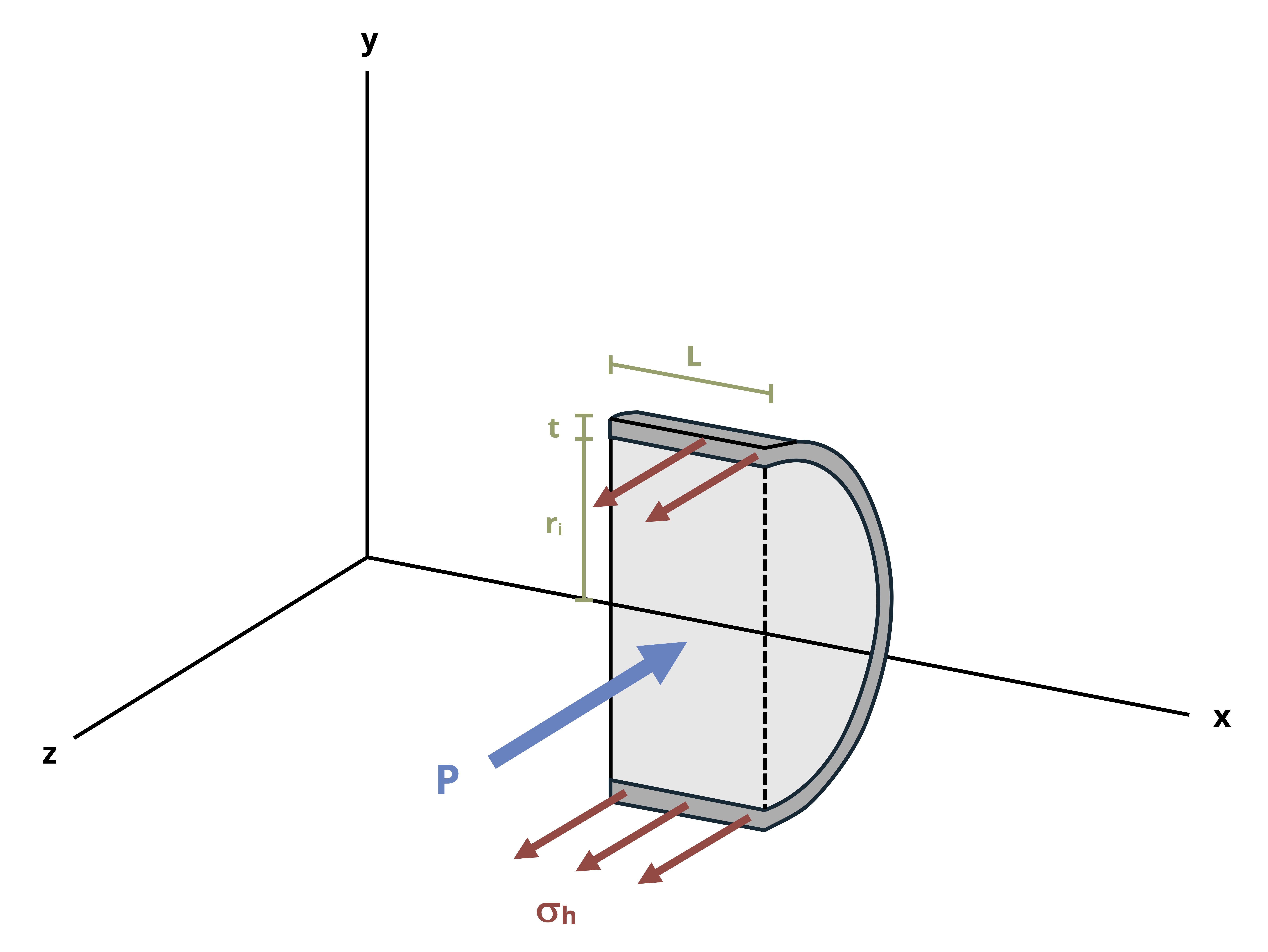
There will again be a stress from the internal fluid pressure (P) and a stress in the walls of the vessel (𝜎H). The fluid pressure acts over an area of \(A=2 r_i L\). The stress in the walls acts over an area of \(A=2 t L\).
By equilibrium we calculate the following:
\[ \sum F_x=\left(\sigma_H\right)(2 t L)-(P)\left(2 r_i L\right)=0 \\ \]
\[ \boxed{\sigma_H=\frac{P r_i}{t}}\text{ ,} \tag{13.2}\]
𝜎H = Hoop stress in the wall of the vessel [Pa, psi]
P = Fluid pressure inside the vessel [Pa, psi]
ri = Inner radius of the vessel [m, in.]
t = Wall thickness of the vessel [m, in.]
Since the radial stress is assumed to be zero, the axial and hoop stresses represent a state of plane stress such as discussed in Chapter 12. Further, since there is no shear stress, the axial and hoop stresses represent the principal stresses. Because the hoop stress is the larger of thes stresses, it is the first principal stress (𝜎1). The axial stress is the second principal stress (𝜎2). The third principal stress acts in the radial direction and has already been assumed to be zero. Figure 13.5 shows a plane stress element representing the stresses in the wall of a cylindrical thin-walled pressure vessel.
Using the methods presented in Chapter 12, we may perform stress transformation on these stresses. Figure 13.6 shows Mohr’s circle for the in-plane and out-of-plane stresses.
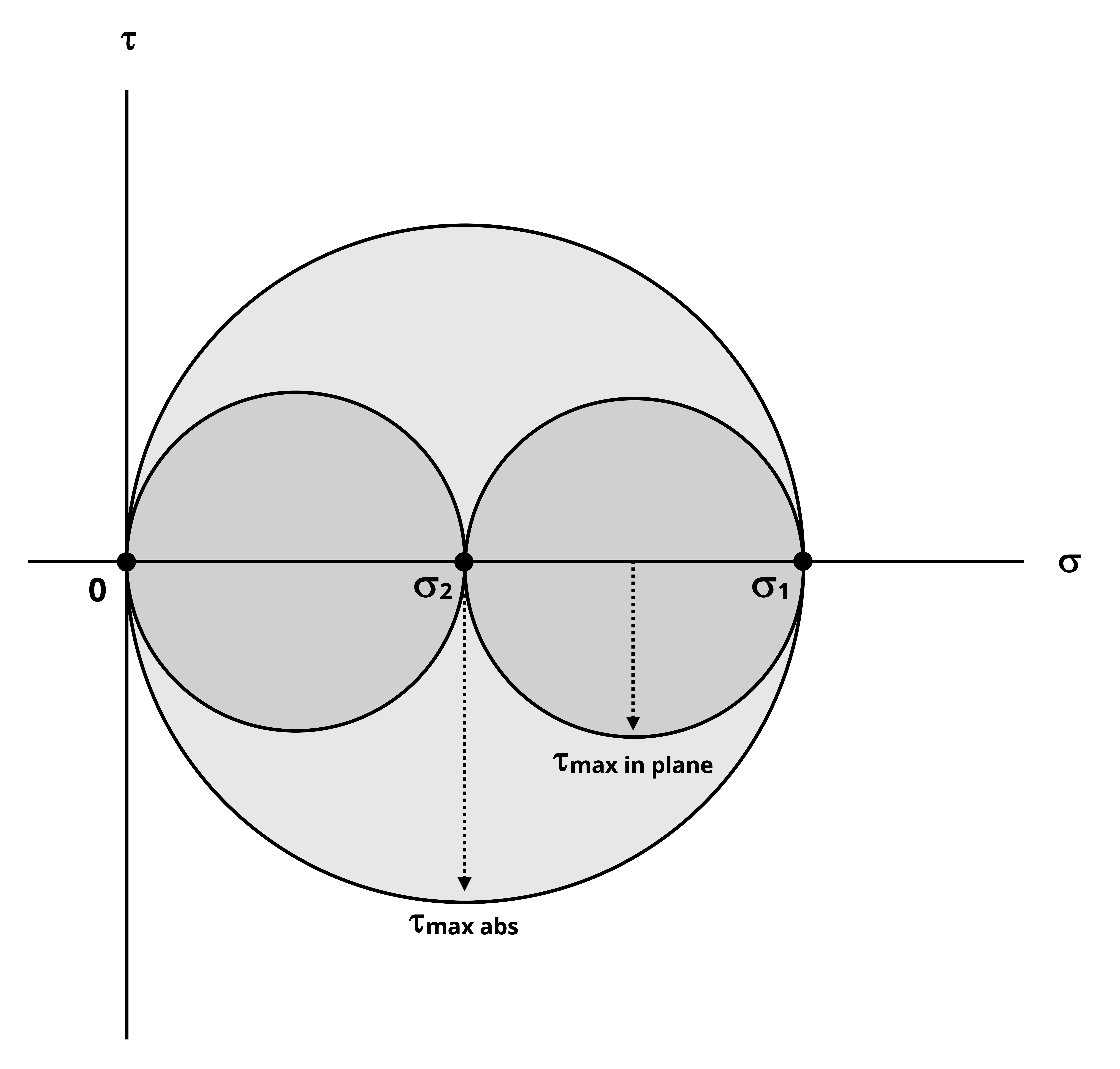
Since the two principal stresses are positive and the third principal stress is zero, it should be apparent that the maximum in-plane shear stress can be determined as
\[ \tau_{max~in~plane}=\frac{\sigma_1-\sigma_2}{2} \]
It should also be apparent that the maximum out-of-plane shear stress will be larger and can be calculated from Equation 12.4.
\[ \tau_{(max)absolute}=\left|\frac{\sigma_{max}-\sigma_{min}}{2}\right|=\frac{\sigma_1}{2} \]
Example 13.1 demonstrates calculation of the principal stresses and maximum in-plane shear stress for a cylindrical thin-walled pressure vessel. Example 13.2 combines the content from this section with stress transformation from Chapter 12 to find the stresses at specific orientations.
Example 13.2
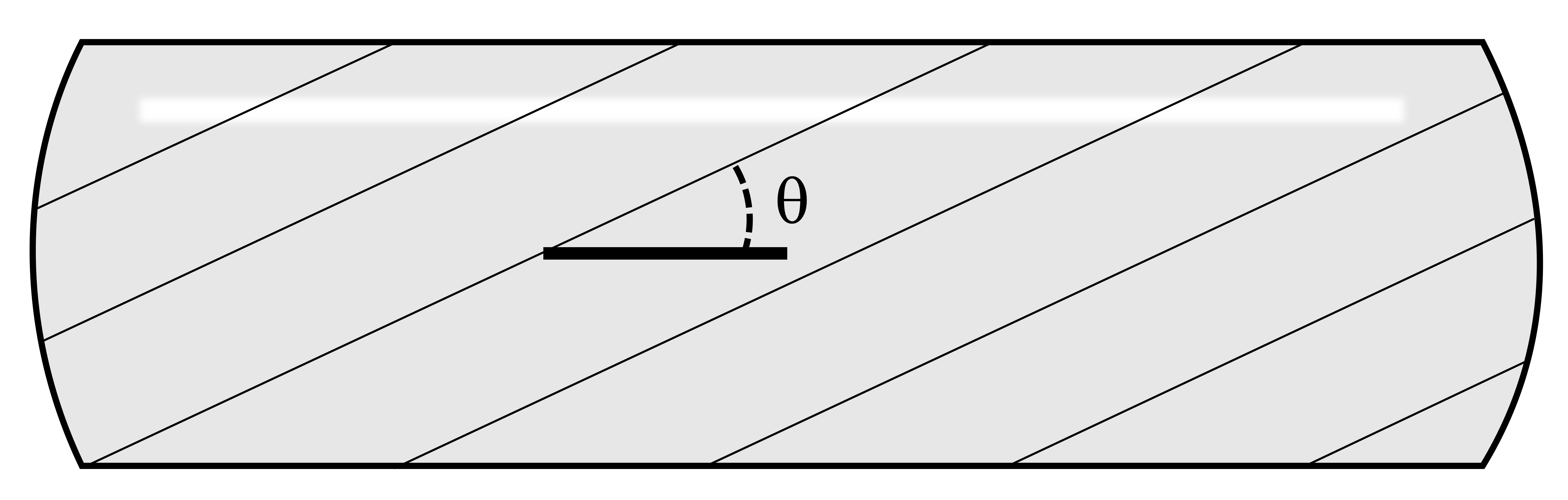
A cylindrical pressure vessel is made by welding a steel plate at an angle of 𝜃 = 25° as shown. The vessel has an outer diameter of 1.5 m and a wall thickness of 40 mm. The vessel contains fluid at a gauge pressure of 5 MPa.
Determine the normal stress perpendicular to the weld and the shear stress parallel to the weld.
First determine the inner radius of the vessel. Wall thickness 𝑡 = 40 mm = 0.04 m.
Outer radius, \(r_o = \frac{1.5{~m}}{2} =0.75{~m}\)
Inner radius, \(r_i = 0.75{~m} - 0.04{~m} = 0.71{~m}\)
Now calculate the axial and hoop stresses.
\[ \begin{aligned} & \sigma_A=\frac{Pr_i}{2t}=\frac{5{~MPa} * 0.71{~m}}{2 * 0.04{~m}}=44.4{~MPa} \\ & \sigma_H=\frac{Pr_i}{t}=\frac{5{~MPa} * 0.71{m}}{0.04{~m}}=88.8{~MPa} \end{aligned} \]
Using the methods shown in Section 12.1, calculate the normal stress perpendicular to the weld. Draw a stress element of a point on the pressure vessel. The axial stress will act horizontally and the hoop stress vertically for this element.
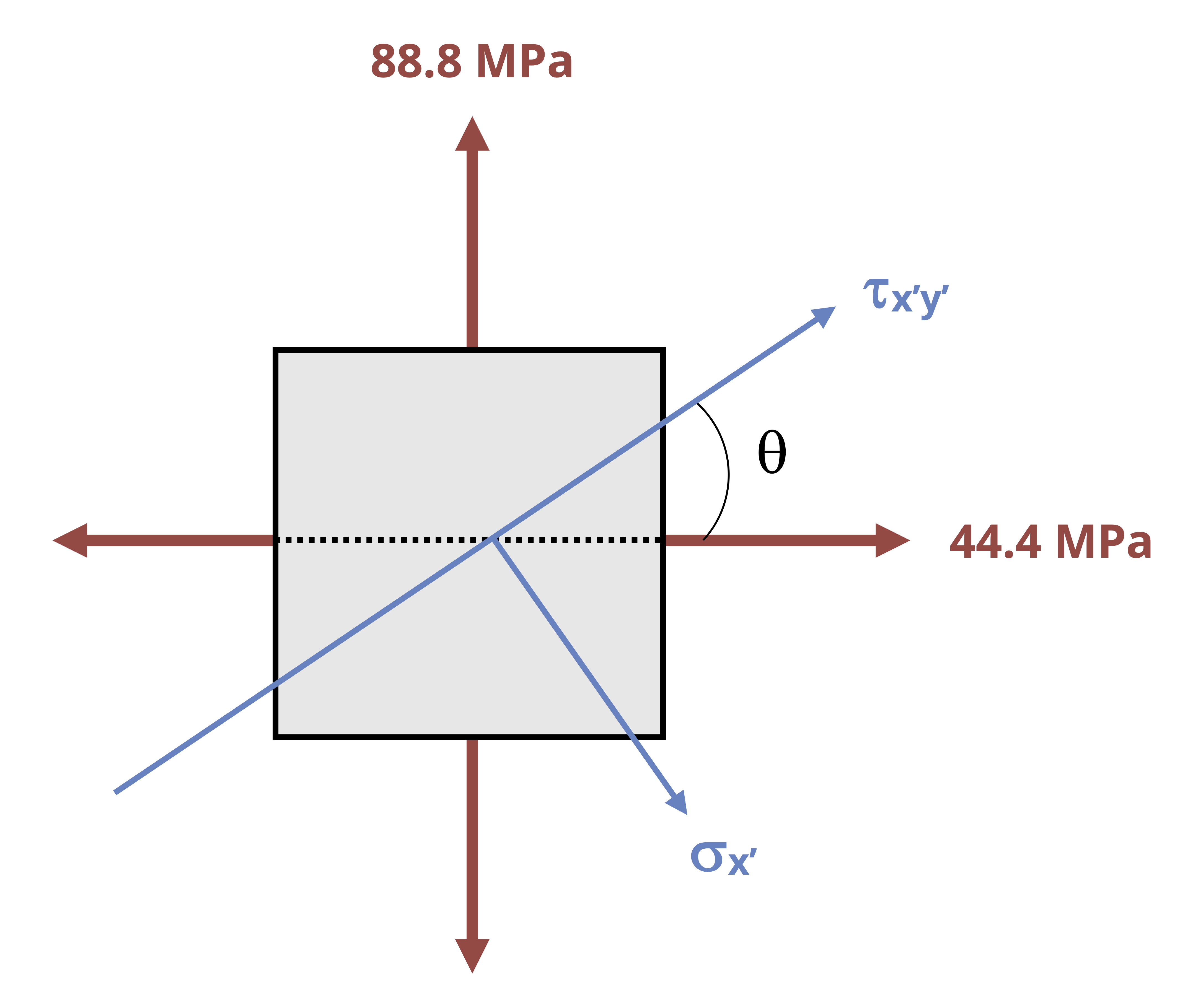
The weld is at an angle of 25° measured counterclockwise from horizontal. The normal stress perpendicular to this weld is therefore at an angle of 65° clockwise from horizontal. Determine the normal stress at this orientation from
\[ \begin{gathered} \sigma_x^{\prime}=\frac{\sigma_x+\sigma_y}{2}+\frac{\sigma_x-\sigma_y}{2} \cos (2 \theta)+\tau_{x y} \sin (2 \theta) \\ \sigma_x^{\prime}=\frac{44.4{~MPa}+88.8{~MPa}}{2}+\frac{44.4{~MPa}-88.8{~MPa}}{2} \cos \left(2 *-65^{\circ}\right)+0 \\ \sigma_x^{\prime}=66.6{~MPa}-22.2{~MPa}*\cos \left(-130^{\circ}\right) \\ \sigma_x^{\prime}=80.9{~MPa} \end{gathered} \]
The shear stress occurs parallel to the weld at an angle of 25° counterclockwise from the horizontal. Determine the shear stress at this orientation from
\[ \begin{gathered} \tau_{x^{\prime} y^{\prime}}=-\left(\frac{\sigma_x-\sigma_y}{2}\right) \sin (2 \theta)+\tau_{x y} \cos (2 \theta) \\ \tau_{x^{\prime} y^{\prime}}=-\left(\frac{44.4{~MPa}-88.8{~MPa}}{2}\right) \sin \left(2 * 25^{\circ}\right)+0 \\ \tau_{x^{\prime} y^{\prime}}=22.2{~MPa}* \sin \left(50^{\circ}\right) \\ \tau_{x^{\prime} y^{\prime}}=17.0{~MPa} \end{gathered} \]
13.2 Spherical Pressure Vessels
Click to expand
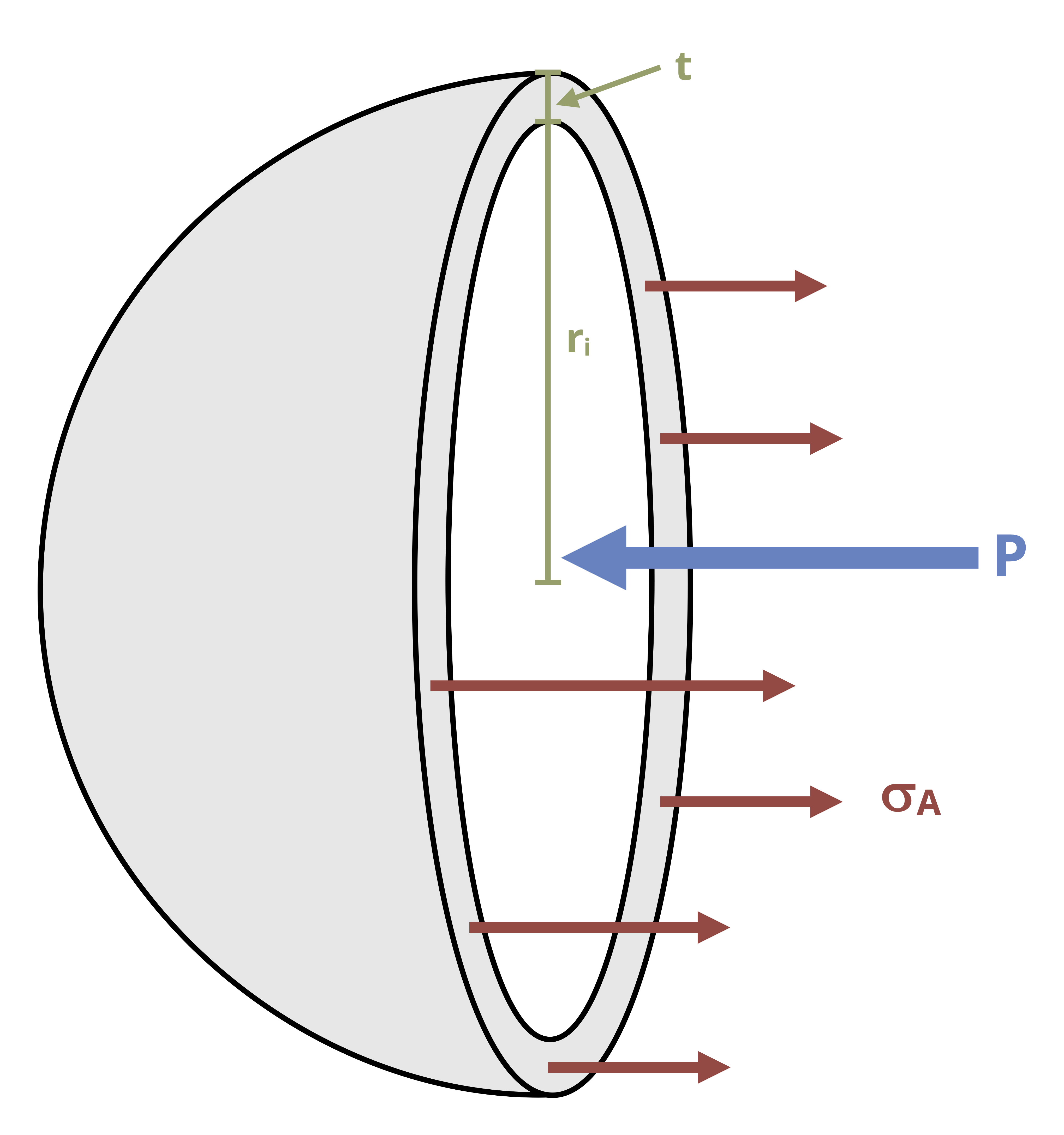
A spherical vessel will yield the same cross-section regardless of the axis it is cut along (Figure 13.7). The stress in the walls of a spherical vessel is the same as the axial stress in a cylindrical vessel.
By equilibrium calculate the following:
\[ \sum F_x=\left(\sigma_A\right)\left(2 \pi r_i t\right)-(P)\left(\pi r_i^2\right)=0 \]
\[ \boxed{\sigma_A=\frac{P r_i}{2 t}}\text{ ,} \tag{13.3}\]
𝜎A = Axial stress in the wall of the vessel [Pa, psi]
P = Fluid pressure inside the vessel [Pa, psi]
ri = Inner radius of the vessel [m, in.]
t = Wall thickness of the vessel [m, in.]
In this case the same stress exists in both principal directions. Again assume that the radial stress is zero, meaning that these stresses again form a state of plane stress (Figure 13.8). There is again no shear stress, so these stresses are the principal stresses.Thus the two principal stresses here are the same.
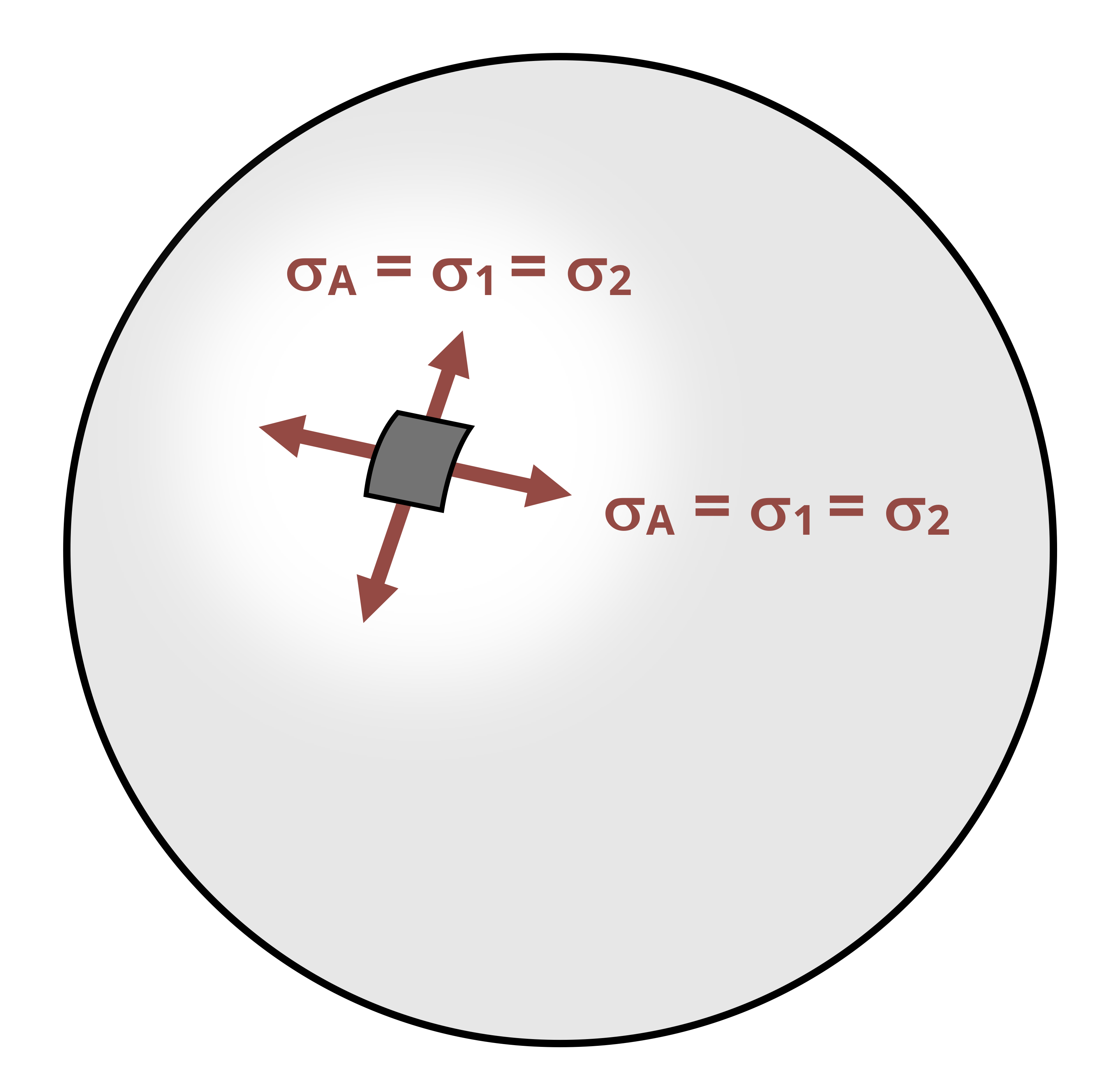
Note that these principal stresses are equal to 𝜎2 in the cylindrical vessel. As such, spherical vessels are stronger than cylindrical vessels because the axial stress (\(\sigma_2\)) is half the hoop stress (\(\sigma_1\)) and there is no hoop stress in a spherical vessel. However, because spherical vessels are more expensive to manufacture, cylindrical vessels remain very common.
We may again use the methods employed in Chapter 12 to perform stress transformation. Figure 13.9 shows Mohr’s circle for the in-plane and out-of-plane stresses.
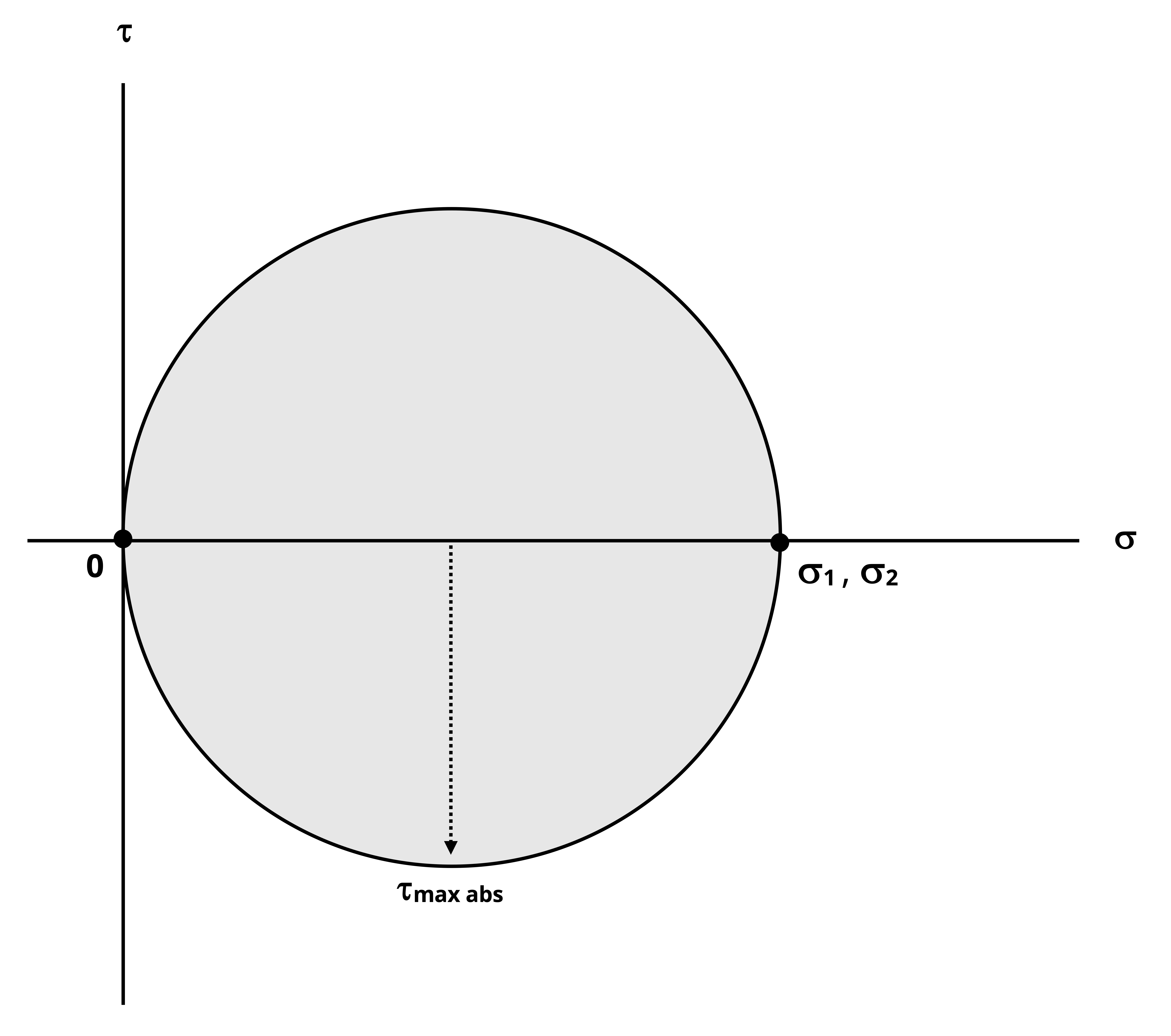
This time 𝜎1 = 𝜎2 and so the in-plane Mohr’s circle reduces to a single point. The maximum in-plane shear stress is therefore zero. The maximum out-of-plane shear stress can be calculated from
\[ \tau_{(max)absolute}=\frac{\sigma_1}{2} \]
Example 13.3 demonstrates the design of a spherical vessel, based on the allowable stress in the vessel walls.
Summary
Click to expand
References
Click to expand
Figures
All figures in this chapter were created by Kindred Grey in 2025 and released under a CC BY license, except for
- Figure 13.1: Some common examples of pressure vessels. A: Tomwsulcer. 2013. Public domain. https://commons.wikimedia.org/wiki/File:Hot_water_heater_with_pipe.jpg. B: James Lord. 2024. CC BY-NC-SA. C: NASA. 2009. No known copyright restrictions. https://flic.kr/p/93mnwD. D: James Lord. 2024. CC BY-NC-SA.